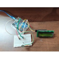
Project Description:
The Heart Beat Sensor using Arduino, pulse sensor, and 16x2 LCD display is a project that measures the heart rate of a person and displays it on a 16x2 LCD display. The project uses a pulse sensor to detect the heart rate of a person. The sensor output is read by an Arduino microcontroller, which processes the data and displays the heart rate on the LCD display.
Working Method:
The pulse sensor is attached to a person's finger or earlobe, and it measures the pulse rate using photoplethysmography (PPG) technology. The sensor output is an analog signal that corresponds to the heart rate. The signal is amplified and filtered using an analog signal conditioning circuit, and then it is connected to an Arduino microcontroller. The Arduino reads the analog signal using the built-in analog-to-digital converter and calculates the heart rate using an algorithm. The heart rate is then displayed on a 16x2 LCD display.
To set up the project, you will need to connect the pulse sensor to the Arduino and the LCD display. You will also need to program the Arduino to read the pulse sensor data, process it, and display it on the LCD display. The programming can be done in the Arduino IDE using the pulse sensor library and the LiquidCrystal library for the LCD display.
Overall, this project provides a simple and cost-effective way to measure heart rate using an Arduino and pulse sensor and display it on a 16x2 LCD display. It can be used in medical applications or fitness devices to monitor heart rate and provide basic health information.
BPM Monitor with Arduino (Heart Beat Sensor)
- Product Code: BPM Monitor with Arduino (Heart Beat Sensor)
- Availability: In Stock
-
₹1,350.00
.png)
